Recently, well once in a while in the last couple years, I’ve had the urge to rebuild some of my old CP/M equipment. Back in the day, the late 70s and early 80s, I ran some California Computer Systems (CCS), CompuPro (aka Godbout and Visan) equipment for a public bulletin board system.
Also used these in business mainly for word processing but spread sheets too. I also used my father’s old Imsai S-100 equipment mostly for playing Startrek. I’ve recently been able to boot the CCS and CompuPro systems, however the Imsai was the worse for wear. It blew it’s fuse protection. My house through the years suffered a fire with resultant water damage as well as an ice storm that caused some flooding during the thaw. As you can see in the following pictures the damage isn’t totally catastrophic but significant.
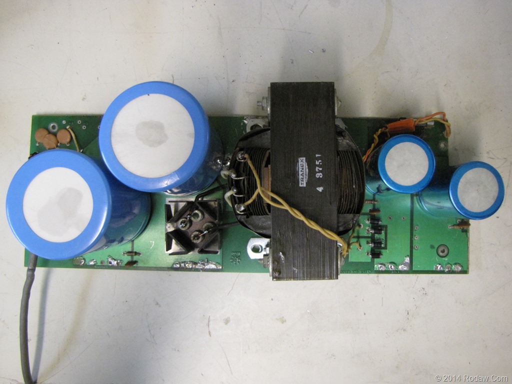
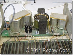 I’ve removed the card edge guide rails and the mounting hardware holding the PS-28U unregulated power supply sub assembly to the main chassis.
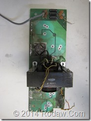 The power supply with capacitors removed.
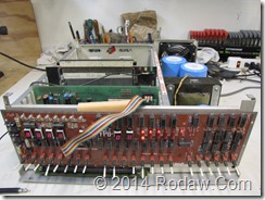
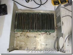 Main frame before cleaning.
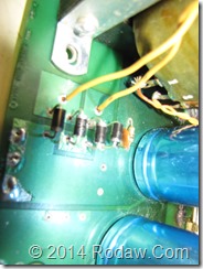
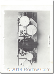 Interesting, this image from my original Imsai documentation shows what appears to be a half wave rectifier, see heatsync near large capacitors, with two diodes. The image above of my actual board has four diodes. The documentation text does indicate four (4) diodes for a full wave bridge rectifier.
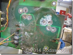
Although the water damage, really just some mudding of the dust, was minimal I thought the capacitors may have shorted or leaked, note the white oxide near the connection holes. The diodes near the lower left in this image are two different kinds, the documentation specifics four (4) of the same diodes MOT MR 501. The outer locations CR4 and CR7 are the correct diodes specified while the center two (2) diodes were HEP 7520. Using the diode test setting on my digital VOM I found that the two MR 501s at CR4 and CF7 were shorted. Checking a few substitution charts I came up with a diode I had on hand an IN5408. I replaced all four to have a matched set. Although mechanically very well connected I found two of the diodes in the bridge rectifier with cold solder connections. A bit surprising considering how much I used this Imsai computer back in the day.
I obtained suitable replacement capacitors from Tedss.Com they also have an eBay store. The capacitors are an identical electrical replacement. The original capacitors are Temple and aluminum cans in color. The spacing on the 10,000uf capacitors is slightly narrower. The blue replacement capacitors are manufactured by Mallory.
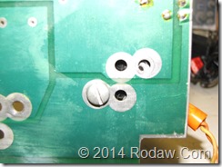 Here is the new capacitor lined up on the mounting connection hole. It’s not an exact match. I don’t like it, I’m still losing a bit of sleep,
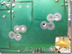 but with a dremel I elongated one of the holes to accommodate the narrower spacing.
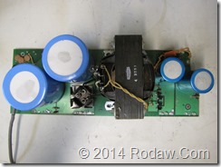 The completed power supply sub assembly rebuild.
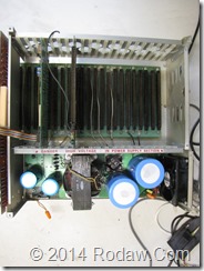 The Imsai was so large and heavy I found it to much for my usual electronics bench and worked on it in my garage.
Over the course of several weeks I’ve put in well over eight (8) hours in researching sources for the capacitors, dismantling and cleaning the power supply and chassis and reassembly. I cringed the first time I plugged it in after having blown several fuses with bright blue flashes while diagnosing the trouble. It came on silently with the whisper quiet cooling fan still functional.
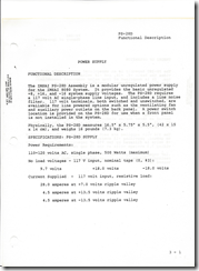 This is the Functional Description page 3 – 1 from the Imsai Power Supply section of the Imsai assembly manual.
I measured the voltage on the repaired power supply as
- +10.02 VDC
- +18.95 VDC
- -19.14 VDC
They were rock solid my DVM goes two places past the decimal. A fairly unscientific measurement of ripple showed less than .015mv. I had a fairly long ground lead that could cause inaccuracies in the ripple reading.
 Here it is cleaned up, plugged in and note the CPU in run state as indicated by this Hexadecimal front panel replacement by Wameco for the original binary Imsai front panel which I have working too.
Pretty fun now that I have it completed. I think I’ll put some RAM in it and try entering a small program with the front panel.
Note; this post updated December 15, 2014 to include voltage readings of repaired unit, and Imsai manual page 3-1.
